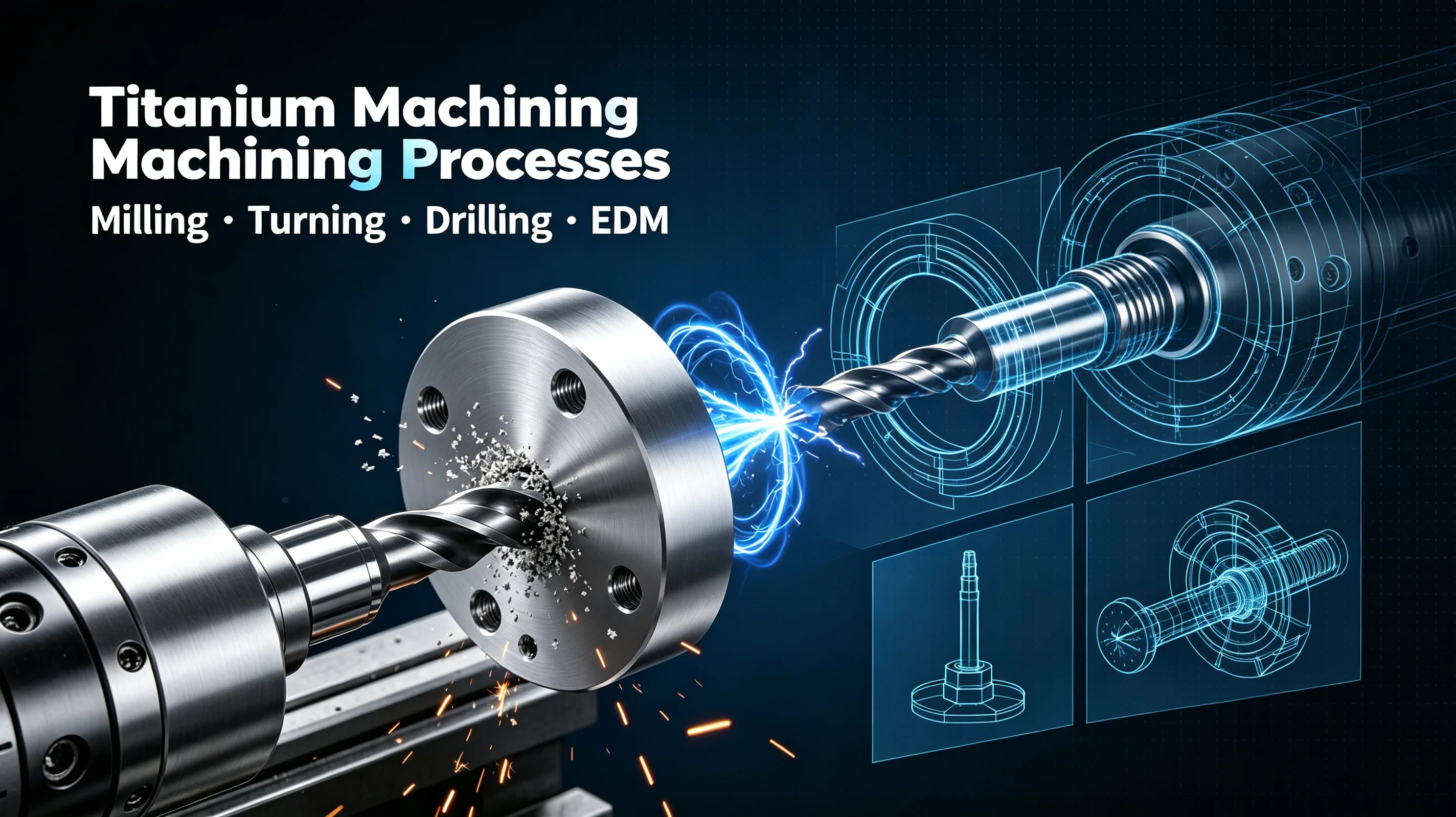
Why process selection matters for titanium
Titanium alloys occupy a narrow operating window between too slow (where galling and built-up edge destroy surface finish) and too fast (where heat concentration burns tools within seconds and triggers work hardening that wrecks the next pass). The shop-floor reality is that the same insert grade that runs 180 m/min in 17-4PH stainless will burn at 60 m/min in Ti-6Al-4V if the chip load is not held constant. The five process families — milling, turning, drilling, EDM, and grinding — each handle a different geometry on the part, and each has its own parameter envelopes and failure modes.
This guide documents the process-selection logic and parameter ranges our shop uses for production titanium parts in Grade 2 (CP), Grade 5 (Ti-6Al-4V), and Grade 23 (Ti-6Al-4V ELI). It is a starting point, not a substitute for first-article trials on your specific machine and tooling combination. Where a parameter range is given, the lower end is conservative for first articles, the upper end is what we typically run in production with stable tooling and verified chip evacuation.
A note on coatings: TiAlN and TiSiN (or AlTiN) coatings are the workhorses for titanium. Uncoated carbide burns fast. PCD and diamond-like coatings have niche uses (high-Si aluminum, graphite) but are not generally recommended for titanium because of chemical reaction at elevated temperature.
Milling (3-axis and 5-axis)
Milling covers the bulk of feature creation on prismatic titanium parts — pockets, slots, walls, contours, and complex aerospace surfaces. The dominant failure mode is thermal concentration at the cutting edge that causes rapid flank wear and chip-pack recrystallization on the workpiece.
Starting parameter envelope (Grade 5 annealed)
| Operation | Cutting speed Vc | Feed per tooth fz | Chip load ap | Axial depth ae | Tool |
|---|---|---|---|---|---|
| Roughing | 50–70 m/min | 0.08–0.12 mm | 30–50% of cutter D | 0.5–1.0×D | Ø10–25 mm carbide, 4-flute, TiAlN, variable pitch |
| Semi-finish | 60–80 m/min | 0.06–0.10 mm | 10–20% of D | 0.3–0.5×D | Same, fresh tool preferred |
| Finishing | 70–100 m/min | 0.04–0.08 mm | 3–8% of D | 0.1–0.3×D | Ø6–12 mm carbide, 4–6 flute, TiSiN, sharp edge |
Beta alloys (Ti-10V-2Fe-3Al, Beta C) drop the upper end by 30–40 percent. CP grades (Grade 2, 4) rise by 10–15 percent.
Tooling and toolpath strategy
Trochoidal milling is the workhorse for deep pockets and slotting. Constant radial engagement of 8–12 percent of tool diameter keeps the chip load steady and evacuates heat with the chip. Full-width conventional slotting in titanium is a leading cause of tool breakage — every entry and exit shock-loads the cutter.
For thin walls (below 1.5 mm thickness), switch to adaptive clearing with radial engagement under 5 percent, and consider a finishing pass with reduced axial engagement (10–20 percent of D) to recover dimensional accuracy after deflection.
Coolant: high-pressure through-tool (1000+ psi / 70+ bar) is preferred. Where unavailable, flood coolant at the maximum pump pressure plus an air blast aimed at the cut zone. MQL alone is insufficient for roughing titanium — heat builds too fast.
Chatter prevention
Chatter in titanium milling is most often caused by:
- Inadequate fixturing that lets the part deflect, especially on thin walls and floors.
- Excessive axial depth of cut in a slender cutter (L/D > 5×).
- Worn tool past the hone radius, increasing rubbing friction.
- Resonance between tooth-pass frequency and a natural mode of the part-fixture system.
The fastest diagnostic: reduce radial engagement by half and re-cut. If chatter disappears, the chip load was too high. If it persists, check fixturing rigidity and tool wear.
Turning
Turning on titanium is dominated by insert grade selection and chip control. Built-up edge (BUE) is the chronic failure mode — at low speeds, titanium welds itself to the insert; at high speeds, the insert crater-wears within minutes.
Starting parameter envelope (Grade 5)
| Operation | Cutting speed Vc | Feed f | Depth of cut ap | Insert |
|---|---|---|---|---|
| Roughing (continuous) | 50–80 m/min | 0.20–0.35 mm/rev | 1.5–3.0 mm | CNMG 120408, GC4325 or equivalent, sharp edge |
| Roughing (interrupted) | 40–60 m/min | 0.15–0.25 mm/rev | 1.0–2.0 mm | CNMG 120408-NM, stronger geometry |
| Finishing | 80–120 m/min | 0.08–0.15 mm/rev | 0.3–0.8 mm | DNMG 150404 or VNMG, wiper geometry |
Chip control
A correctly-broken chip is short, blue or straw-colored, and curls tightly. A long, stringy, silver chip is a sign of too low a feed or wrong chip-breaker geometry — it will wrap around the workpiece and either scratch the finish or stop the machine.
For deep profile turning (axial length > 3×D), reduce feed by 20–30 percent to keep the radial force low and avoid deflection.
Drilling and tapping
Drilling titanium is where the chip evacuation problem becomes acute. Unlike aluminum or steel, titanium chips do not break cleanly — they form long, hot, stringy segments that weld themselves to the drill flute if not cleared. The consequence is drill breakage (often with the part scrap) or work-hardening of the hole wall that ruins a reaming or finishing operation downstream.
Drill geometry
Use solid carbide drills with through-tool coolant (not brazed-tip HSS). A 140-degree point angle (split-point if possible) reduces thrust and improves centering. Polished or TiAlN-coated flutes reduce chip adhesion.
For hole depth beyond 4×D, switch to gun-drilling or deep-hole drilling with peck cycles. Standard twist drills fail predictably between 5×D and 8×D depending on the grade.
Peck cycle for standard drilling
For a hole of depth 5×D in Grade 5:
- Peck depth: 1×D initially, decreasing to 0.5×D as depth increases.
- Full retract to clear chips every peck. Do not skip retracts to save cycle time — that is where chips pack and drills break.
- Reduce feed by 20-30 percent in deeper pecks.
- Through-tool coolant pressure at maximum available (typically 1000+ psi).
Tapping
Tapping titanium is a controlled failure: the tap will eventually break, and the question is whether that break happens before or after the hole is complete. Strategies:
- Use forming taps (thread rolling) rather than cutting taps where the print allows — they produce no chips and work-harden the thread for higher fatigue strength.
- For cutting taps, use TiCN or TiAlN coated, spiral-point (for through holes) or spiral-flute (for blind holes).
- Reduce tapping speed to 30-50 percent of steel — typically 5-10 m/min in Grade 5.
- Use tapping fluid with high extreme-pressure content, not generic cutting oil.
- For blind holes, ensure at least 3 thread pitches of clearance beyond the cut depth for chip room.
If a tap breaks, EDM extraction is faster and lower-risk than mechanical extraction in titanium. Plan for it.
EDM (wire and sinker)
EDM is selected when:
- The feature is in a hardened condition (>HRC 40) that makes conventional milling impractical.
- The feature has sharp internal corners (R0.0 to R0.1) that a milling tool cannot reproduce.
- The feature is a micro-slot, thin web, or complex 2D shape in the range 0.1-2.0 mm.
- The tolerance is tight (sub-0.02 mm) and the part is in a difficult-to-fixture geometry.
EDM does not contact the workpiece, so the work-hardening tendency of titanium is irrelevant to the cut itself. What matters is the recast layer left by the EDM process — a thin (~5-15 micrometer) martensitic-alpha layer that must be removed for fatigue-critical parts.
Wire EDM parameters for titanium
- Wire: brass-coated, 0.25 mm diameter is standard; 0.20 mm for fine features.
- Flushing: submersed in deionized water; through-the-nozzle flushing for tall parts.
- Cut strategy: 2-pass minimum — first pass at high power for speed, second pass at low power (skim) for surface finish and recast reduction. Three or four passes for tight tolerance or fatigue-critical surfaces.
- Surface finish target: Ra 0.8 micrometer achievable; Ra 0.4 micrometer with skim passes.
- Recast layer: 5-15 micrometer typical. Remove via light pickling (HF/HNO3 mix), light abrasive blasting, or chemical milling — per the print’s surface-finish spec.
Sinker EDM for 3D features
Sinker EDM is slower than wire but can produce 3D cavities and sharp corners that milling cannot. Common titanium applications: forging-die trimming, micro-features in medical implants, small-batch prototype cavities.
Copper or graphite electrodes, polarity negative (workpiece positive), servo-controlled gap. Deionized water dielectric. Expect 5-20 percent slower material removal than in tool steel at the same electrical settings.
Process selection flowchart
Use this simplified decision tree when a new titanium part arrives at quoting:
- Rotational feature (OD/ID, threads, grooves)? → Turning (lathe or mill-turn).
- Prismatic feature (pocket, slot, contour)? → Milling (3-axis or 5-axis depending on access).
- Hole? → Drilling (standard), gun drilling (>4×D depth), EDM (micro or non-round).
- Sharp internal corner (R0.0-R0.1) or hardened condition? → EDM (wire or sinker).
- Micro-feature <0.5 mm? → EDM or micro-machining with specialized tooling.
- Surface-finish-critical and tight tolerance (Ra <0.4 micrometer, +/-0.01 mm)? → Grinding after rough machining.
For most production parts, the answer is 80 percent milling + 15 percent turning + 5 percent drilling/EDM. The split shifts toward EDM for medical implants (micro-features) and toward turning for rotational aerospace hardware (discs, rings, hubs).
Common defects and prevention
| Symptom | Most likely cause | Prevention |
|---|---|---|
| Chatter marks on wall | Excessive radial engagement or worn tool | Reduce ae by half; check tool wear; verify fixturing rigidity |
| Recast layer on EDMed surface | Inadequate skim passes or wrong polarity | Add skim pass at 20 percent power; verify polarity |
| Burr at hole exit | Drill geometry or breakthrough parameters | Use 140-degree split-point; reduce feed at breakthrough |
| Work-hardened surface | Tool dwell or insufficient coolant | Verify coolant pressure and flow; reduce radial engagement |
| Built-up edge on insert (turning) | Too low speed, wrong chip-breaker | Raise Vc by 10-15 percent; switch chip-breaker geometry |
| Tap breakage | Insufficient chip clearance or wrong speed | Increase clearance; reduce speed; consider forming tap |
| Alpha case formation | Excessive heat input above 600 degree C | Reduce Vc and ae; verify coolant; verify part is not heat-affected post-cut |
Cost and lead-time comparison
The shop-floor economics of process choice (rough ranges for a Grade 5 part, all features considered):
| Process | Typical machine hourly rate | Best for |
|---|---|---|
| 3-axis milling | $80-150 | Prismatic parts, medium complexity |
| 5-axis milling | $150-250 | Complex aerospace surfaces, single-setup parts |
| Turning | $80-120 | Rotational parts, OD/ID features |
| Wire EDM | $120-200 | Hardened features, sharp corners, micro-slots |
| Sinker EDM | $130-220 | 3D cavities, forging die trim |
| Gun drilling | $150-250 | Deep holes >4×D, small diameters |
Lead time tracks process setup time more than cycle time. EDM has the longest setup, but the shortest cycle once running — making it economical for small batches of complex features that would otherwise require custom milling cutters.
Conclusion
Process selection for titanium is the intersection of geometry, material, tolerance, and economics. The right answer is rarely a single process — most production parts use three or four of the five process families in sequence. The parameters in this guide are starting points: validate them against your machine, your tooling, and your specific lot of material before committing to production. When in doubt, run the first three parts conservatively and inspect — the cost of a parameter mistake on titanium is high, but the cost of uncertainty is higher.
For project-specific parameter recommendations or to submit a drawing for process review, request a quote. Our engineering team reviews each RFQ against the geometry, material, and tolerance spec before any tooling is ordered.